Divecomputer
The dive computer is now in the final phase.
After many small projects, there is now a plan.
Images, hardware and software will follow soon.

|
Tauchcomputer.orgSelbstbau Elektronik für's Tauchen und Meer |
The dive computer is now in the final phase.
After many small projects, there is now a plan.
Images, hardware and software will follow soon.
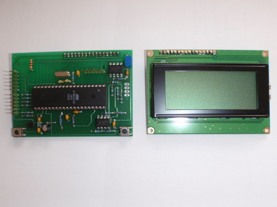
For many new projects, is a universal board useful as a development platform.
Therefore, the board has been generated, a ATMega (32/64), 2 OP-Amp’s and includes a display.
The op-amps are wired back to the amplification of small signals (eg O2 sensors) with amplification factor of 20.
As Shown are 2 × 16 × 16 or 4 line LCD display is used.
For input two keys are available (eg for a menu).
An ISP programming header is also present, may be programmed directly from AVR Studio.
For output signals are 6 ports brought out.
A 5 V voltage regulator is also provided, as well as the wiring of the internal reference voltage for the AD converter
The ATMega is powered by an external crystal of 8Mhz
| Ansicht der Universalplatine, links die CPU Platine mit allen I/O’s, rechts die Anzeige 4×16 Zeichen LCD |  |
Selbstbau eines O2 Sensoren Testers
From the project OLED HUD came the idea to build one O2 sensors tester.
O2 sensors age with time (galvanic cell) and thus have no more linear characteristic. Especially in the range of pO2> 1.0 Curves then fall flat, or the sensor reaches 1.6 pO2 not even the final value.
To test this, sensors may therefore be a pressure-tight measuring chamber in and out with compressed air (max 9 bar of regulators) is applied. The pressure increase is a fixed flow allows small to (pressure increase over time).
The sensors are measured while the electronics and values on the display graphically illustrated them. This allows linearity and full scale (1.6pO2) is determined to be very good.
What features are realized
The first consideration was now the chamber with oxygen filled. Good idea, but has a hook ![]() is because in the time in which the measuring chamber filled to 100% oxygen, there is no increase in pressure in the chamber (ambient) only when the chamber is closed (solenoid valve) causes a pressure increase, which can then be recorded and the pressure sensor. This results in pO2 = 1.0 to no curve on the display. (Y = const pressure, x = sensor value rises)
is because in the time in which the measuring chamber filled to 100% oxygen, there is no increase in pressure in the chamber (ambient) only when the chamber is closed (solenoid valve) causes a pressure increase, which can then be recorded and the pressure sensor. This results in pO2 = 1.0 to no curve on the display. (Y = const pressure, x = sensor value rises)
So now air was selected as the measuring medium. The pressure chamber is closed and the pressure continues to rise (Y-axis pressure is increasing with time). In a final value of about 9 bar, the sensors should then reach a pO2 of 9 x 12:21 = 1.89 pO2. This results in a series of measurements can, the pressure increase delayed by a needle valve (about 0.5 liters per minute).
Why building a HUD itself?
The HUD on the market are usually implemented with one or more single or multi-colored LED’s. An article on rebreatherworld.com came the idea of a HUD from a miniature OLED build.
I found them in a large auction house and obtained a 0.95 “color OLED graphic. It uses the SSD1331 controller for which there was already finished in the net libraries (www.microcontroller.net).
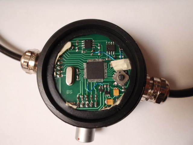
Served as control electronics, the circuit foundation stone of the dive computer. However, it should all fit in a “can” of TecMe.
Therefore, the circuit has been realized in SMD.
In the can even fit a standard battery LiIo what the power supply of course easier.
What features has the OLED_HUD
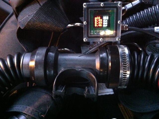
The display then changes its colors of pO2:
RED: is <0.65 and> 1.5
YELLOW: when> = 0.65 to <1.1 and> 1.3 to <= 1.5
GREEN: when> = 1.1 and <= 1.3
The heading “pO2” will change your color accordingly, being always the “most” dangerous color appears.
| The OLED HUD electronics. |  |
| The display in detail. It is attached to a Dolphin mouthpiece. Possible to see the three sensors in pO2 (red) behind the sensor voltages. |  |